

Overview
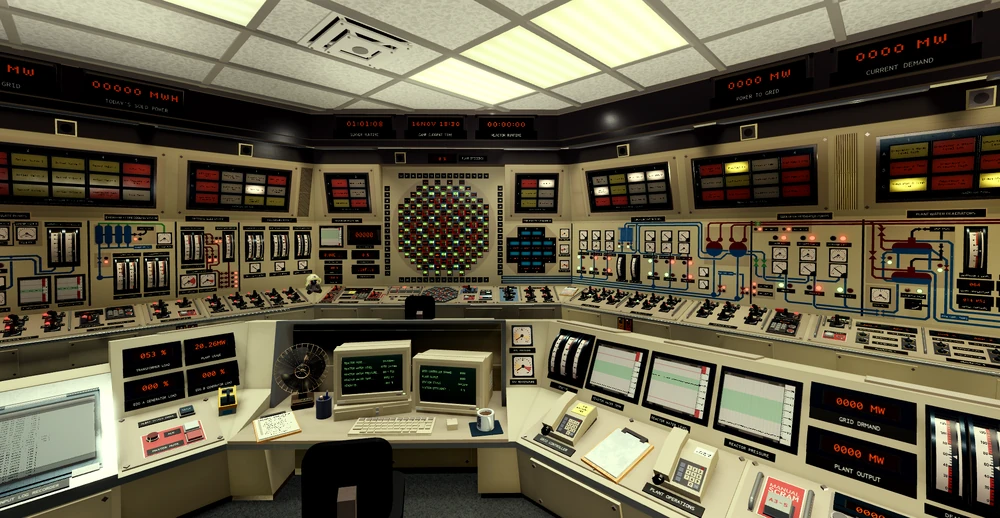
The control room is found on Level 3, accessible via the Lower Level. It houses most major controls for Oakridge’s operations, including control rods, turbines, and electrical systems.
Operators use this room to monitor and adjust plant behavior in real time. Pumps here feature three speeds: red (1), yellow (2), and green (3).
How to Access
- Enter through Staff Intake.
- Proceed to the elevator and select LL (Lower Level).
- Use Plant Access A and take the elevator to L3.
- Turn left twice to reach the Control Room.
Parameters
This section aims to give you a general idea of what values are considered safe, and what equipment should
be used to keep said values in check.
Reactor power: 0-4800 MW, mainly kept in check by the control rods.
Reactor water level: The feed limiter attempts to keep the water at 250 inches, so if there is any
deviation, something is wrong (make sure it's on). Low water level may cause a raise in reactor temperature
and efficiency, hence why you may see people in public servers running the reactor at low levels. High water
levels can be fixed with the circ drains, and lowering of the amount of feedwater pumps in service. Low
level means you don't have enough feedwater pumps running. A raise in feedwater pump usage may lower the
deaerator level, and in turn, hotwell level.
(Water flows as such: Reactor (recirculation) > Turbines > Hotwell > Deaerator > Feedwater > Reactor).
Below 120 inches the feedwater pumps wont be able to raise the level anymore, and ECCS should
be used.
Reactor temperature: Should be kept below 1500 degrees. At 1800 degrees there is a chance of experiencing a
fuel channel leak. The main way to control the temperature is by using the recirculation pumps. If only one
or a few sectors are hot (seen on the heat display on the rod control panel), you may insert control rods in
those sectors to get them to match the rest of the reactor.
Reactor pressure: Generally you shouldn't run into this issue, however you may use the relief valves to keep
the pressure in check.
Deaerator level: Should be kept in the green, however some people get it lower to increase efficiency. If
you have a high deaerator level, check if the overflow valve is on on the deaerator panel. If you are facing
a low deaerator level, start more condensate pumps, but keep an eye on hotwell level.
Deaerator temperature and pressure: The temperature has no limit, but higher temperatures can raise the
amount of power being delivered to the grid. It is raised/lowered by the steam inlet valve. This valve might
also influence the pressure. The pressure should be kept below 350 PSI. Lowered by the relief valves.
Hotwell level: Anything above 0. Low level, the make-up may be used. High level, the hotwell drains.
Turbine pressure: Below the red line (960), lowered by the bypass valve when the turbine isn't in
operation.
Rod Control Panel
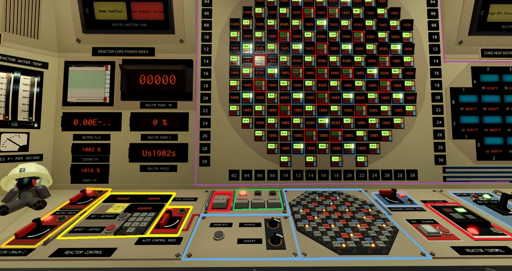
Here you can withdraw or insert the control rods. Withdrawing them raises the power, inserting them lowers it. The automatic controls rods can be used to stabilize reactor power at any desired amount (preferably within 200 MW of the current reactor power level). Turning the automatic rods off will revert their position back to 50%, so be careful. The shutdown rods prevent the reactor power from raising, or the control rods from being withdrawn. The main display shows you the status of each control rod (Automatic in red, shutdown in blue.). The heat distribution display shows how hot each sector of the reactor is. Generally you don't want any of the sectors to exceed 1400-1600°F, as detailed above. The modes work as such:
- Mode 0, shutdown (This mode is used when the reactor is offline, and restricts the removal of the shutdown rods.)
- Mode 1, Start-up (0-1500 MW)
- Mode 2, operating (1500+ MW)
The Offline Core Cooling (along with the shutdown rods) keep the reactor cold while offline; Should be turned off during operation. The circ drains can also be found on this panel. In the event of an emergency, the АЗ-5 (often refered to as AZ-5) can be utilized to quickly insert the rods back into the reactor. They are automatic by default however, you can set it to manual operation with the key locked switch located right of the rod selection panel.
Turbines
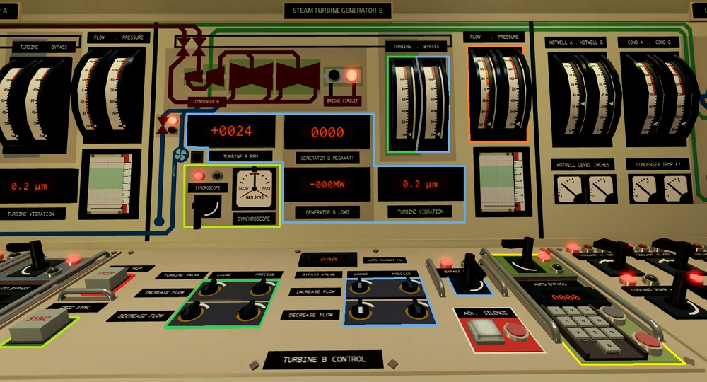
The turbines send power to the grid, which gets you points.
In order to start the turbines you must disengage turning gear by calling engineering. In order to sync to the grid, you must get the RPM close to 1800 ( ± 30 RPM.). RPM can be manipulated primarily with the turbine valve, however the bypass valve offers finer control. The flow gauge shows you how fast you are increasing your turbines speed.
To sync, you just watch the synchroscope and press the sync button once you hear the buzzer. After syncing, raise the turbine valve a little to avoid reverse power, then proceed with the checklist.
The bleed valve is used to match the pressure between the turbines
After going online, you should utilize the automatic bypass to hold the demand; Divide the demand by 2 and insert it into both keypads.
Load rejection can occur if there is a sudden drop in power usage. It is mainly an issue before going online, when too many pumps are turned off at once.
The proper way to shut down the turbines is to lower power, de-sync the turbine (via the generator breakers), lower the RPM and open the bypass.
The option to manually trip the turbines is also there, but it's rarely ever used, during normal operations it should not be pressed as it causes operators to resync the turbine, wasting time and missing out on energy production
Condenser coolant
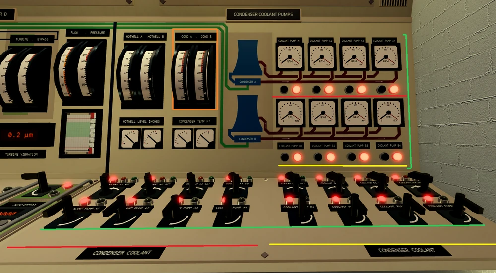
The condenser coolant pumps control the rate at which steam can condense back into condensate (water recovered from the condenser). Each condenser has its own loop, loop A and loop B. A coolant is pumped through the condenser to cool the steam back into water; this heat is then transported to a cooling tower, where it can be cooled to remain effective.
High condenser coolant temperature is caused by an insufficient number of pumps and can lead to high outlet pressure in the turbines, followed by vibration and if left unchecked, tripping the turbine; However, an abundance of pumps can hinder efficiency, resulting in less points being earned.
Condensate, Hotwell and Water system
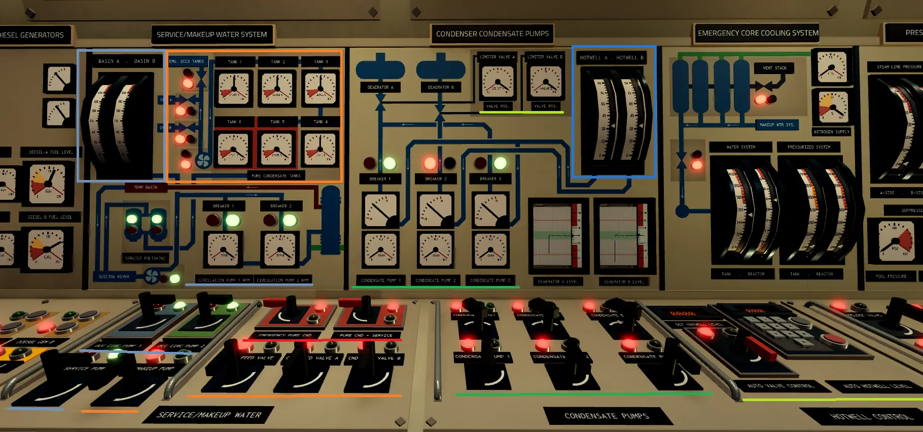
The condensate pumps move water from the hotwell to the deaerator, controlling the deaerator level. The hotwell collects the water (condensate) from the condenser, which is located below it. To prevent the deaerator from being overfilled, the overflow valve (located on the deaerator panel) should be on at all times.
Similarly to the feedwater pumps, the condensate pumps can also cavitate and trip; This is caused by a low hotwell level.
The Auto valve control can be used to prevent the hotwell tanks from getting overfilled, and the level can be set via the keypad. For efficiency and a hotter water temperature, higher levels are generally better.
If the hotwell tank gets too full, the hotwell drains can be used (located on in the ECCS section, to be added).
During emergencies when water is lost from the system or the reactor needs to be cooled while it is offline, the Plant's service/makeup water system comes into play, the Pure CND tanks store water from the local Susitna river which first gets treated by service polishers, after that the water can be used to make up water in both hotwells and the ECCS water tank for emergencies.
The service pump provides cool water from the river for OCC pumps and cooling tower basins, as the water cooling is not 100% effective, and it gets lost as water vapour which can be seen coming out of the cooling towers, to prevent the condenser coolant circuit from drying up slowly the service pump provides make up water into cooling tower basins.
OCC pumps, pump water provided by service pump into the heat exchanger to cool down the reactors primarily circuit when the reactor is offline, the now heated up water gets sent into a temporary basin to be cooled down, the water then gets sent back into the Susitna river.
The make-up pump transfers water from the CND tanks into hotwells A, B and ECCS water tank, in order to refill those you need to also open the feed valves, 1 for eccs, and 2 for each hotwell.
The emergency pure cnd and pure cnd-service are used in case of emergencies, emergency pure cnd allows you to use the emergency CND tanks 5-6 to put water in the 1, 2, 3, and 4 tanks to then put water in hotwell or eccs, pure cnd service can use battery power to power itself in case if you lose offsite power, the pump acts as service pump but providing water only to OCC pumps at a cost of also using the CND tanks water supply instead of taking water from the river.
Deaerator
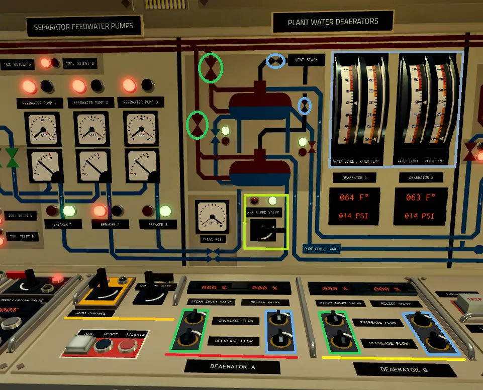
The deaerator's true purpose is to remove impurities from the feedwater, using steam in order to heat the water up. This power plant features 2 deaerator, and similarly to the condenser coolant, has 2 loops (loop A and loop B), receiving steam from their respective steam drums, and water from the condensers.
The deaerator has 2 valves, those being the steam input and relief. The steam input lets more steam in, raising the temperature, and increasing the pressure slightly, while the relief vents steam out, lowering the pressure.
The A-B Bleed valve mixes the water of the 2 deaerator, helping the water level equalize on both deaerator.
For proper deaeration (water cleaning), it needs to be configured at 250C and 100PSI. This can be done by using the automatic control
The water level of the deaerator is mainly managed on the condensate panel; however, this panel features the overflow valve, which prevents flooding of the deaerator.
Feedwater
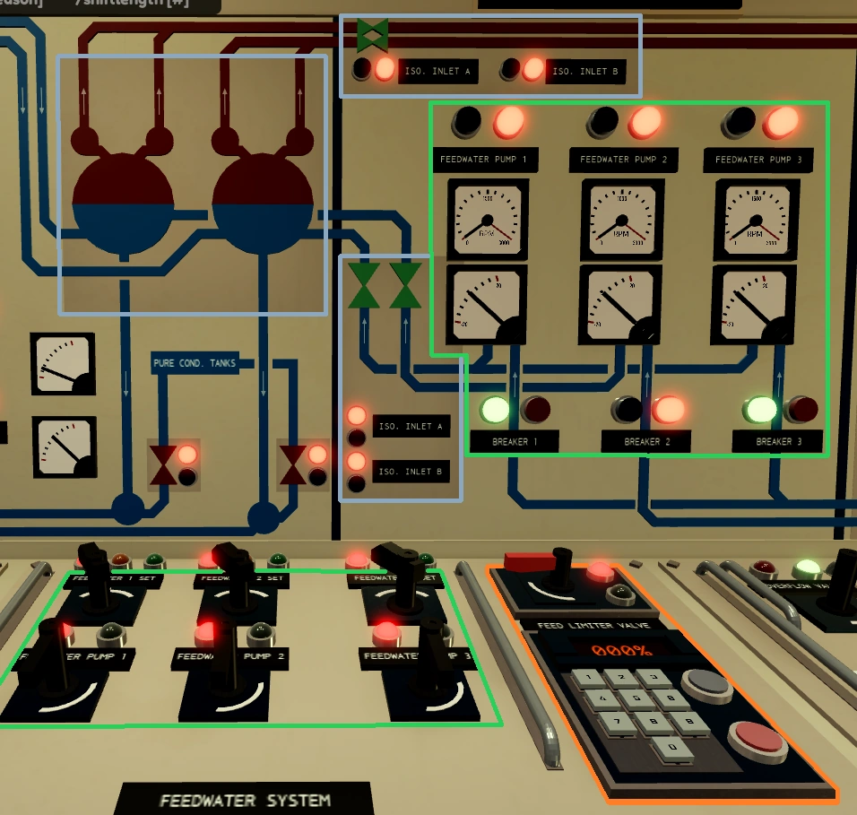
The Feedwater controls how much water enters the steam drums (RPV); The water level can be checked on the rod control panel, to the left of it by the relief valves, or on the Central status panel. The pumps take water from the deaerator; If the deaerator level is too low, the pumps will start to cavitate and eventually trip. An insufficient number of them will cause the water level to drop, which can cause the reactor to scram.
The feed limiter valve is similar to the overflow valve; it prevents water from flooding the reactor pressure vessel. Turning the switch on will make it automatic by limiting the feedwater intake upwards of 50% to keep the water level; however, it can also be used in manual mode, via the keypad (with the switch off).
The isolation valves prevent feedwater from entering and steam from exiting the RPV. A closed isolation valve will cause the feedwater pumps to trip if they are already on or are turned on.
Reactor Circulation
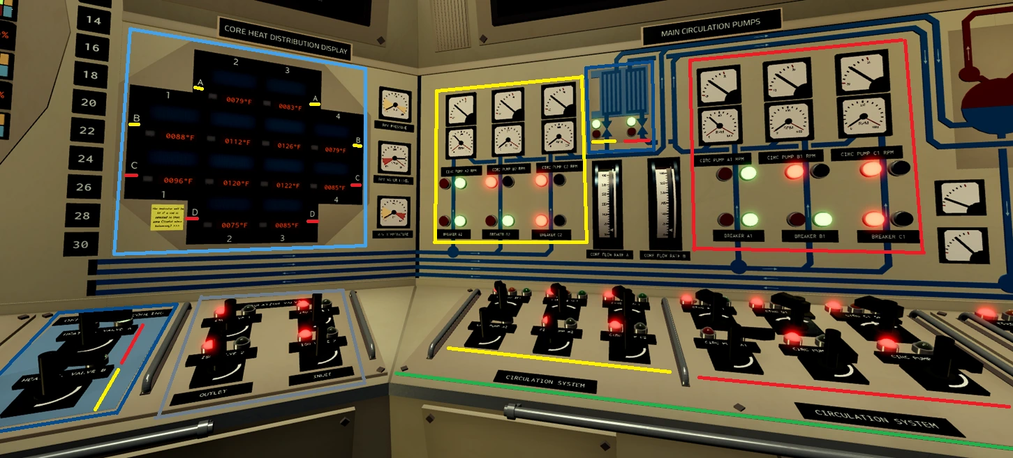
The reactor's main circulation pumps (MCPs) take water from the reactor and run it back through the steam drums (RPV); Two loops (Loop A and Loop B) for their respective steam drums (RPV). Their main function in-game is trading heat to steam for the turbines.
The heat of the reactor fuel can be seen on the heat distribution display. A reactor that is too cold won't boil steam and might flood the reactor (≲900°F); meanwhile, a reactor that is too hot has a higher risk of fuel channel leaks (≳1800°F). It is recommended to find the sweet spot for the best efficiency.
Each loop has their own heat exchanger valve, when the valves are open the water that exited main circulation pumps gets redirected to the heat exchanger to cool down by exchanging heat with water from OCC pumps, this allows to cool the reactor while its offline due to it still heating up even after shutting down.
Additionally, loop A mainly circulates the water through reactor's sectors (see on heat distribution display) C and D, while loop B through sectors A and B, also, the isolation valve switches can be seen.
ECCS and Pressure relief system
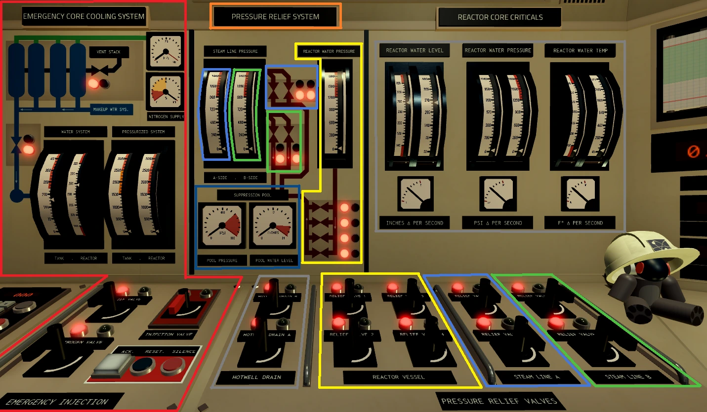
During emergencies that require quick reaction, the Emergency Core Cooling System (ECCS) and Pressure Relief System (Relief Valves 1-4) allow you to quickly inject water into the reactor or relieve pressure from the reactor or steam lines.
The Emergency Core Cooling System (ECCS) quickly injects water into the reactor, to do so you need to make sure that the ECCS tank has at least 144 inches of water at all times and is pressurized by opening the Nitrogen Valve to at least 1500 PSI, once ECCS is filled with water and is pressurized, the Injection Valve can be open to inject water into the reactor vessel, note, if reactor water pressure is above ECCS circuit pressure the water from reactor will backflow to ECCS tank, causing the water level in reactor to drop further, you can pressurize the tank further or open the Reactor Vessel relief valves for a short period of time.
In order to refill the ECCS water tank you must make sure to depressurize the tank by opening ECCS Relief Valve, after depressurizing go to the water service/makeup panel and activate make-up pump and open ECCS feed valve.
The Pressure Relief System is used to quickly relieve pressure from the Reactor Vessel with valves 1-4, Steam line A with relief valves 5-6 and Steam Line B with relief valves 7-8.
The relieved steam/water pressure gets sent into a suppression pool to naturally cool down, in extreme cases of relieving too much pressure (most of the times from reactor) the suppression tank can get overpressureized and cause all relief valves to automatically close.
Relieved pressure from reactor or the steam lines means that water got lost from the primary circuit, to make up the lost water, make-up water in Hotwells.
The Hotwell Drain Valves and Reactor Core Critical's panel informing on reactors water level, water temperature and water pressure while also providing information about how rapidly these parameters change can also be seen.
The Electrical Panel
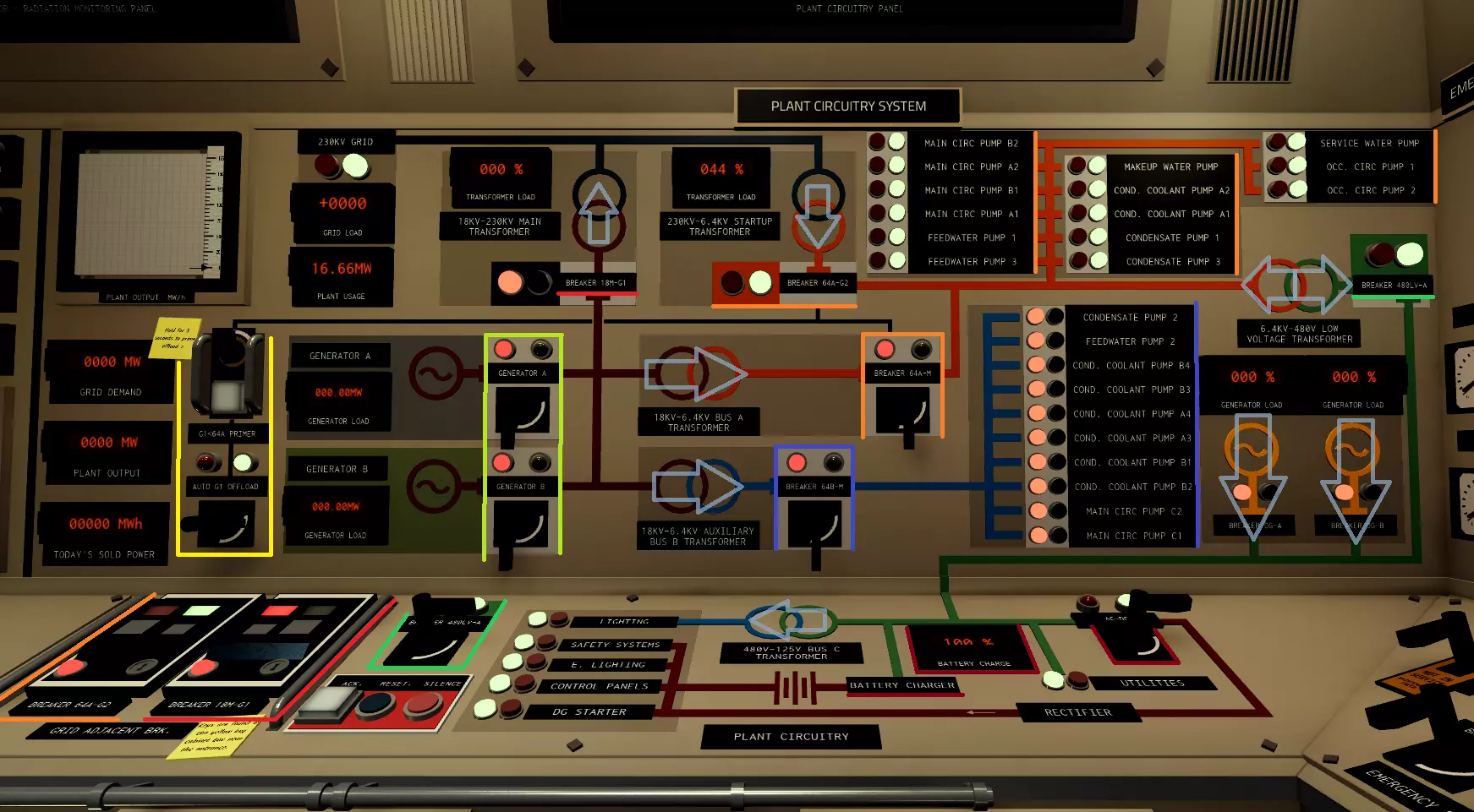
The electrical panel is used to control the flow of electricity throughout the facility and offsite (aka.
the grid).
The 64A-G2 breaker (Startup transformer) is used to power Bus A (orange line) during the
reactor's off-time and start-up. Bus A contains all the pumps that can be powered by the startup
transformer, with the rest being hosted in Bus B (blue line), which cannot be powered by the startup
transformer.
Breakers 64A-M and 64B-M have the functionality of moving power from the
turbine generators to the 2 buses. After the run-up of turbine A, both of these breakers
should be closed (on), assuming the turbine is producing enough excess power to provide for them. 18M-G1 (The Main transformer) connects the turbine generators to offsite (black), allowing
them to provide power to the grid.
In the event that the turbines are unable to power the buses, for example, due to a trip, the automatic G1 offload (if primed and active), will close the breaker to the startup
transformer, providing power to bus A.
The Low Voltage line (green) powered by either the 480LV-A (turbines, startup transformer)
or the diesel generators, hosts the lights, AC-DC converter and the battery charger, which are connected to
several critical systems (crimson). Turning off the AC-DC breaker will cause the power from the low voltage
line to flow directly through the battery, making it unable to charge.
You may have noticed that the 480LV-A breaker goes both ways, that is because diesel generators can actually
back-feed into Bus A. This requires both diesel generators to be active and Bus A to be un-powered. The
diesel generators provide less power than the startup transformer and should only be used in
emergencies.